
CNC Machining Company Tolerances and Surface Finishes: What a Buyer Can Realistically Expect
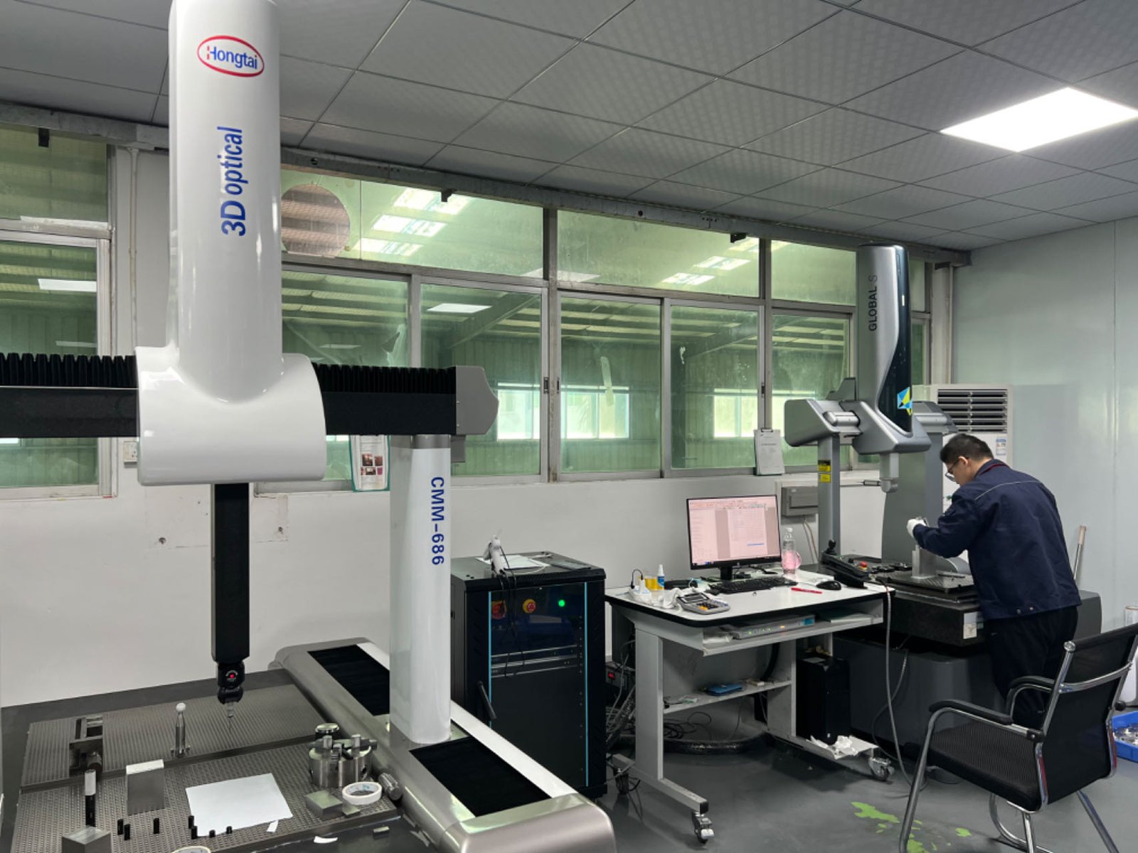
The realistic tolerance and surface finish for a machined part are not single numbers — they are bands tied to process, volume, and measurement. A milling or turning center holds ±0.003 mm as standard work; grinding reaches ±0.002 mm; and whether either number survives a production run is a question of process capability, Cpk, and inspection, not of what a capability sheet claims. This guide explains what a CNC machining company can honestly hold feature by feature, which Ra finishes each process delivers, how volume changes the equation, and what evidence settles a tolerance claim before you commit.
Why is a realistic tolerance a band tied to process, not a number on a brochure?
A tolerance is a cost instruction and a process instruction at the same time. When a drawing calls out ±0.003 mm, it is telling the shop to route that feature to a milling or turning center and to measure it on a CMM. When it calls out ±0.002 mm, it is telling the shop to route the feature to a grinder, because that is the only process family that removes material in fine enough increments to hold the band. The realistic tolerance for a part is therefore the set of bands its features can actually be held to by the processes that make them.
The distinction between "the tolerance a machine holds" and "the tolerance a shop promises" is where buyers get burned. A brochure that lists ±0.003 mm and ±0.002 mm side by side is describing what each process can do. What it does not say is which of your features will be routed to which process, and what happens when a drawing asks for grinding-level precision on a feature that only needs milling. The honest conversation starts with the drawing: name the functional features, and the process and the realistic band follow.
This matters more at volume than at prototype, because at volume the tolerance is multiplied by every unit of the run. A tolerance that is barely achievable in the one-off — held by an operator's care and a CMM confirmation — becomes a scrap generator when it repeats across ten thousand parts unless the process is capable of holding it consistently. That is why the realistic-tolerance question and the volume question are the same question.
Which tolerance can each process actually hold on a CNC machining company's floor?
Every process has a band it holds comfortably and a band it only reaches with extra care. The bands below are the working numbers a capable CNC machining company quotes against, and they are verified by measurement rather than assumed:
- 3-axis CNC milling — ±0.003 mm. The default for prismatic parts: housings, brackets, plates, pockets. A milling center holds this band by construction when the fixture is rigid and the tool is sound.
- 4-axis and 5-axis milling — ±0.003 mm. The same size band, reached while cutting multiple faces in one setup. The advantage is fewer re-clamps, which is where positional error creeps in.
- CNC turning — ±0.003 mm. The default for round parts: shafts, pins, bushings. Turning holds roundness and diameter well because the work rotates about its own axis.
- Mill-turn — ±0.003 mm. Round parts with milled features, held in one clamping so the turned and milled features stay concentric.
- Precision grinding — ±0.002 mm. The tighter band, reserved for bearing seats, sealing faces, and roundness-critical surfaces. Grinding removes material in micron-sized increments, which is why it reaches the finer band, and why it is slower and costlier.
The practical rule for a drawing: put ±0.003 mm on the features that mate, locate, or rotate against another part, and leave the rest on a general band such as ISO 2768. Reserve ±0.002 mm for the one or two surfaces that genuinely need a ground finish. A drawing that stamps the tightest band on every dimension is routing the whole part through grinding — whether it needs it or not.
Which part features defeat a tight tolerance no matter the machine?
Some features cannot hold a tight band regardless of the process assigned to them, and knowing the list saves a buyer from specifying the impossible:
- Thin walls. A wall thinner than roughly a millimeter vibrates and deflects under the cutter, so it wanders in and out of tolerance. The fix is design — thicken the wall or support it — not a tighter callout.
- Deep pockets and deep holes. The longer the tool overhang, the more it deflects. A deep, narrow pocket drifts at the bottom no matter how carefully it is cut. Depth-to-width ratio is the constraint, not the machine's capability.
- Long, slender turned parts. A shaft that is many diameters long whips under the cutting force and bows between centers. The realistic band on a slender shaft is looser than the machine could hold on a short, stiff one.
- Thin features near the edge. A narrow rib or a boss at the part's boundary deflects as the cutter passes, and the deflection shows up as size error on the finished feature.
- Features after heat treatment. Heat treatment moves dimensions. If a bore must be tight after hardening, it is ground after the heat-treat step, which adds a process and a cost that a drawing tolerancing the pre-heat state quietly misses.
The pattern is that geometry defeats tolerance more often than machines do. A shop that says "we can hold ±0.003 mm" is describing its machines; the honest shop also tells you which features on your drawing will not hold it because of geometry. That second sentence is the one that protects your schedule.
How does the material change the tolerance a part can honestly hold?
Material changes the tolerance story in two ways: how easily the part holds its size in the cut, and how it moves afterward. Aluminum machines fast and holds its shape well, which is why it is the default material for tight-tolerance prototypes. Its weakness is thermal — aluminum expands about twice as much as steel for a given temperature change, so a large aluminum part measured warm and cold can read differently. Stainless holds dimensions better through temperature but work-hardens in the cut and traps heat, punishing a dull tool. Titanium is slower still, with low thermal conductivity that concentrates heat at the cutting edge.
The grade matters as much as the family. Free-machining grades — 303 stainless, 12L14 steel, C360 brass — cut cleanly and predictably, which protects the tolerance through the run. Work-hardening grades like 304 need proper tooling and feed strategy, because a timid cut can gall the surface and move the dimension. A drawing that names the grade tells the shop what it is cutting; a drawing that says "stainless" leaves the machining behavior to chance.
Incoming material is XRF-checked against the mill certificate before it reaches the machine, so the grade you specify is the grade that is cut. That verification matters to tolerance because a substituted alloy — softer or harder than specified — changes the machining behavior and can push an in-tolerance process out of band. The material check is the first link in the tolerance chain.
Which surface finishes are realistic, and what does each Ra require?
Surface finish is the second half of the specification, and it follows the same logic as tolerance: each Ra value is tied to a process, and specifying finer than the function needs buys cost without function. The realistic finish ladder on a CNC machining company's floor looks like this:
- Ra 3.2 µm — standard milling and turning. The default surface that comes off the tool in normal cutting. Fine for general faces, brackets, and non-sealing surfaces.
- Ra 1.6 µm — fine milling or light grinding. Achieved with a finishing pass or lighter cuts. Suits locating faces, bearing seats, and ordinary mating surfaces.
- Ra 0.8 µm — precision grinding. Reached when the surface is ground. Typical work: sealing faces, rotating fits, and sliding surfaces where roughness would affect function.
- Ra 0.4 µm and finer — lapping or polishing. Reserved for optical, metrology, or special sealing surfaces. Each step below 0.8 µm adds a process and a per-part cost.
The buyer rule mirrors the tolerance rule: specify the Ra the function needs and nothing finer. A seal face at Ra 0.8 µm is worth its cost. A cosmetic surface at Ra 0.8 µm is a tax the drawing imposes for no functional return. And like tolerance, the finish should be specified only where the surface actually seals, slides, or seats, because each finer rung is a finishing step repeated on every part of the run.
How does volume change the tolerance and finish equation?
Volume changes the tolerance equation through process capability. On a one-off, a part can be held in tolerance by careful setup and full inspection. On a production run, that approach fails — one bad setup or one drifting tool creates thousands of out-of-tolerance parts before anyone notices. The volume question is whether the process holds the band consistently, and the answer is measured by Cpk, process capability on production data.
Cpk is the honest version of a tolerance claim at scale. A Cpk of 1.67 on a critical characteristic means the process is centered and tight enough that the band will hold across the run, with scrap controlled. A Cpk of 1.33 is the general floor for less critical characteristics. The numbers matter because they connect the tolerance to the process data: a shop quoting Ppk ≥ 1.67 at the initial study on critical characteristics and Cpk ≥ 1.33 in production on general characteristics is describing what its production process actually delivers, not what a brochure hopes.
Ask for the study behind the number — a Cpk figure from a job like yours, with a named characteristic and a stated sample size. That is the difference between a tolerance that is real and a tolerance that is printed. At volume, the tight-tolerance question is really a capability question, and the capability question is answered by data, not by adjectives.
What does the tolerance-to-cost relationship look like across the volume tiers?
Tolerance and surface finish sit on the cost curve at every volume, but the shape of their cost changes as quantity grows. On a one-off, a tight tolerance costs the extra setup and inspection time on that single part. On a production run, the same tolerance costs a per-part increment repeated across every unit — plus the scrap risk if the process drifts. The general tolerance is the cheapest because it rides the standard process. A specific tight callout on a functional feature is the honest premium. And a drawing that tightens everything is the expensive mistake, because it routes the whole part to grinding and inspection whether each dimension needs it.
The finish ladder stacks the same way. Ra 3.2 µm comes off the standard cut. Ra 1.6 µm adds a finishing pass or light grinding. Ra 0.8 µm adds precision grinding. Below that, lapping or polishing adds another process. Each rung is a per-part cost that volume multiplies, which is why finish, like tolerance, should be specified only where the surface does real work.
The drawing discipline that keeps both curves low is the same: reserve the tight tolerance and the fine finish for the features that mate, seal, slide, or rotate, and leave everything else on a general band. The factory's guide to how tolerances move the price at each volume tier puts the arithmetic on the cost curve, and the quality page explains how Cpk and measurement back the numbers.
What proof should you ask for before a tolerance or finish claim is real?
A tolerance or finish claim becomes real only when it is backed by measurement from a job like yours. Before you commit, ask for the evidence that settles the claim:
- A CMM report from a real part. Measured values on the critical dimensions, not a sentence saying the part is in tolerance. The report is the product as much as the metal is.
- A Cpk study with a named characteristic and sample size. A Cpk number without the study behind it is marketing. The study shows the process is capable, not just the one part.
- A surface roughness trace or measurement. A finish claim of Ra 0.8 µm should come with the instrument reading that confirms it, not with a photo.
- The XRF result on the material lot. The tolerance only holds if the material is what was specified, so the grade verification closes the first link in the chain.
A supplier that produces these documents is delivering a verifiable tolerance. One that answers with adjectives is asking you to trust a hope. The tolerance you put on the drawing is only as good as the evidence that comes back with the part, so the evidence question belongs in the RFQ, not in the post-mortem.
Which tolerance and finish mistakes repeat on real orders?
Four mistakes account for most tolerance and finish surprises, and all four are visible on the drawing before a chip is cut:
- Tolerancing everything to the tightest band. A drawing that stamps ±0.003 mm or ±0.002 mm on every dimension routes the whole part to the most expensive process. Tolerance selectively — tight only where the function demands it.
- Specifying a finish finer than the function needs. Ra 0.8 µm on a cosmetic surface is a per-part tax. Specify the finish only where the surface seals, slides, or seats.
- Ignoring geometry limits. A thin wall or deep pocket will not hold the band no matter what the process. Geometry defeats tolerance more often than machines do.
- Trusting a capability sheet instead of a Cpk study. The number on the brochure is a wish; the study from a job like yours, with a named characteristic and sample size, is a fact.
The buyer who specifies selectively, respects geometry limits, and asks for measurement evidence gets a part that is on tolerance and on budget. That is the whole discipline.
Frequently Asked Questions
What tolerances can a CNC machining company realistically hold?
Milling, turning, and mill-turn hold ±0.003 mm as standard work; precision grinding reaches ±0.002 mm. The realistic band for your part depends on which features need which process, and whether the process is capable of holding the band across your quantity — measured by Cpk, not by a brochure.
Which surface finish should I specify?
Specify the Ra the function needs and nothing finer. Ra 3.2 µm comes off standard milling and turning; Ra 1.6 µm needs a fine pass; Ra 0.8 µm needs grinding; Ra 0.4 µm and finer needs lapping or polishing. Call out the fine finish only where the surface seals, slides, or seats.
What is the difference between ±0.003 mm and ±0.002 mm?
±0.003 mm is the working band of a well-maintained milling or turning center, held by construction and confirmed by a CMM. ±0.002 mm is the band only a grinder reaches, because grinding removes material in micron-sized increments. The tighter band is slower and costlier, so reserve it for bearing seats and sealing faces.
Can a CNC machining company hold tight tolerances at high volume?
Yes, if the process is capable, which is what Cpk measures. A Cpk of 1.67 on critical characteristics means the process is centered and tight enough to hold the band across the run with controlled scrap. Ask for the Cpk study with a named characteristic and sample size, not just a number.
Why do some features not hold tolerance no matter the machine?
Geometry defeats tolerance more often than machines do. Thin walls vibrate and deflect, deep pockets drift as the tool overhangs, slender turned parts whip under the cutting force, and features can move after heat treatment. The honest shop tells you which features on your drawing will not hold the band because of geometry.
How does material choice affect achievable tolerance?
Material affects how easily a part holds its size in the cut and how it moves afterward. Aluminum machines fast but expands more with heat; stainless holds dimensions better but work-hardens; titanium is slower with low thermal conductivity. Incoming material is XRF-checked against the mill certificate so the grade you specify is the grade that is cut.
What proof should ship with a tight-tolerance part?
A CMM report with measured values on the critical dimensions, a Cpk study with a named characteristic and sample size where volume justifies it, and a surface roughness measurement for any finish claim. The evidence is the product as much as the metal is.
Need a realistic tolerance and finish specification for your part?
Send the drawing, the material, and the quantity to [email protected] or call +86 13126536955. You will get a design-for-manufacturing review that flags which tolerances and finishes earn their cost — with the CMM and Cpk evidence that makes the claim real.